Objective: This lab will provide the understanding of how to configure frame relays on Cisco routers. Creating an frame relay links is a fundamental skill that network engineers need to be able to perform.
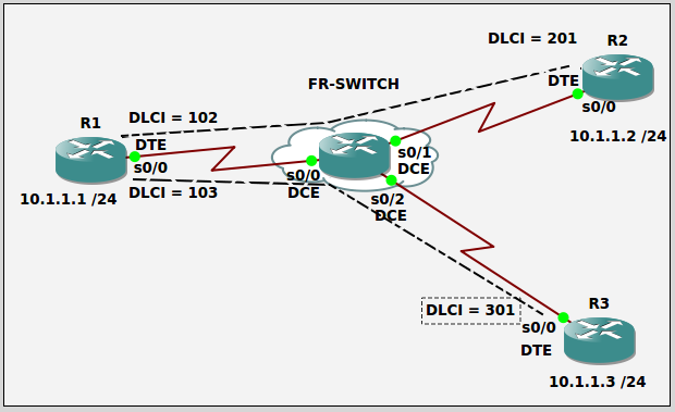
Purpose: Frame relay is a WAN technology used to send frames over virtual circuits that are locally identified as Data Link Connection Identifier (DLCI) numbers. In this lab we will use a preconfigured frame relay switch which can be found here. The purpose will be to configure three remote office routers to enable frame relay communication from the remote offices to each other office.
Topology:
Task 1: Use the proper cables to connect the ports as shown in the topology.
Task 2: Configure host names on routers R1, R2, and R3 as shown in the topology.
Task 3: Configure IP addresses as shown in the topology.
Task 4: Enable frame relay switching and configure the interfaces for frame relay on each router in the topology.
Task 5: Verify configuration is working on all routers by pinging from R1 to R2 and R3.
Task 6: Enable full mesh between all offices. (this will disable inverse ARP)
Task 7: Configure static frame relay routes to R1 on R2 and R3 to fix inverse ARP being disabled.
Task 8: Verify full configuration is working on all routers and ping from every device to every other device.
ANSWER:
Task 1:
We need to use a crossover cables to connect two like devices.
Task 2:
R1
Router>en
Router#conf t
Router(config)#hostname R1
R1(config)#
R2
Router>en
Router#conf t
Router(config)#hostname R2
R2(config)#
R3
Router>en
Router#conf t
Router(config)#hostname R3
R3(config)#
Task 3:
R1
R1#conf t
R1(config)#int s0/0
R1(config-if)#ip address 10.1.1.1 255.255.255.0
R1(config-if)#no shut
R2
R2#conf t
R2(config)#int s0/0
R2(config-if)#ip address 10.1.1.2 255.255.255.0
R2(config-if)#no shut
R3
R3#conf t
R3(config)#int s0/0
R3(config-if)#ip address 10.1.1.3 255.255.255.0
R3(config-if)#no shut
Task 4:
R1#conf t
R1(config)#frame-relay switching
R1(config)#int s0/0
R1(config-if)#encapsulation frame-relay
R1(config-if)#frame-relay intf-type dte
R1(config-if)#no shut
R2#conf t
R2(config)#frame-relay switching
R2(config)#int s0/0
R2(config-if)#encapsulation frame-relay
R2(config-if)#frame-relay intf-type dte
R2(config-if)#no shut
R3#conf t
R3(config)#frame-relay switching
R3(config)#int s0/0
R3(config-if)#encapsulation frame-relay
R3(config-if)#frame-relay intf-type dte
R3(config-if)#no shut
Task 5:
R1#show frame-relay pvc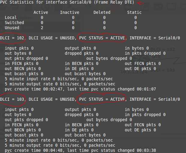
R1#show frame-relay map
Here is where we run into problems with running a virtual lab. From the GNS3 docs “GNS3/Dynamips doesn’t emulate the physical layer which is why the serial connections work even though they are both DCE.” and Packet Tracer does not support frame relay switching from a router perspective. Entering the above command is blank because we are unable to set our office routers side to DTE to obtain clocking and the frame-relay route (Just one of many reason I prefer real equipment). If in a real lab you will get the below.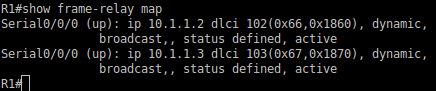
R2#show frame-relay pvc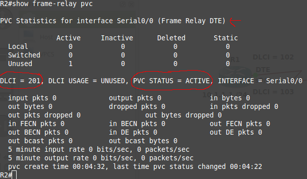
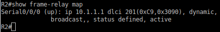
R2#show frame-relay map
R3#show frame-relay pvc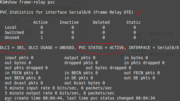
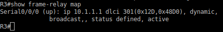
R3#show frame-relay map
Task 6:
R2(config)#int s0/0
R2(config-if)# frame-relay map ip 10.1.1.3 201 broadcast
R3(config)#int s0/0
R3(config-if)# frame-relay map ip 10.1.1.2 301 broadcast
Task 7:
R2(config)#int s0/0
R2(config-if)# frame-relay map ip 10.1.1.1 201 broadcast
R3(config)#int s0/0
R3(config-if)# frame-relay map ip 10.1.1.1 301 broadcast
Task 8:
R1#ping 10.1.1.2
R1#ping 10.1.1.3
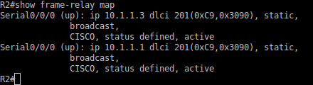
R2#show frame-relay map
R2#ping 10.1.1.1
R2#ping 10.1.1.3
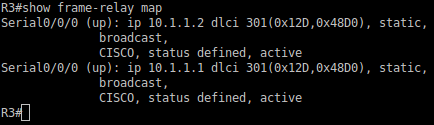
R3#show frame-relay map
R3#ping 10.1.1.1
R3#ping 10.1.1.2

Pingback: HOW TO Setup a Frame Relay Switch | Chris Nadeau