Objective: This lab will provide the understanding of how to configure frame relay point-to-point interfaces on Cisco routers. Creating point-to-point frame relay links is a fundamental skill that network engineers need to be able to perform.
Purpose: Frame relay is a WAN technology used to send frames over virtual circuits that are locally identified as Data Link Connection Identifier (DLCI) numbers. In this lab we will use a preconfigured frame relay switch which can be found here. The purpose will be to configure three remote office routers to enable frame relay communication from the remote offices to each other office without the need of static routing. (This lab can be continued from the frame relay static config lab, you will just need to remove the ip addresses from the serial interfaces before beginning.)
Topology: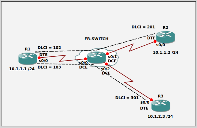
Task 1: Use the proper cables to connect the ports as shown in the topology.
Task 2: Configure host names on routers R1, R2, and R3 as shown in the topology.
Task 3: Enable frame relay switching, configure the sub interfaces for point-to-point frame relay, and configure the sub interface IP addresses on each router in the topology.
Task 4: Verify configuration is working on all routers by pinging from R1 to R2 and R3.
Task 5: Enable full mesh between all offices with a default ip route on R2 and R3.
Task 6: Verify full configuration is working on all routers and ping from every device to every other device.
ANSWER:
Task 1:
We need to use a crossover cables to connect two like devices.
Task 2:
R1
Router>en
Router#conf t
Router(config)#hostname R1
R1(config)#
R2
Router>en
Router#conf t
Router(config)#hostname R2
R2(config)#
R3
Router>en
Router#conf t
Router(config)#hostname R3
R3(config)#
Task 3:
R1
R1(config)#frame-relay switching
R1(config)#int s0/0
R1(config-if)#encapsulation frame-relay
R1(config-if)#frame-relay intf-type dte
R1(config-if)#int s0/0.102 point-to-point
R1(config-if)#ip address 10.1.1.1 255.255.255.0
R1(config-if)#frame-relay interface-dlci 102
R1(config-if)#int s0/0.103 point-to-point
R1(config-if)#ip address 10.1.2.1 255.255.255.0
R1(config-if)#frame-relay interface-dlci 103
R1(config-if)#no shut
R2
R2(config)#frame-relay switching
R2(config)#int s0/0
R2(config-if)#encapsulation frame-relay
R2(config-if)#frame-relay intf-type dte
R2(config-if)#int s0/0.201 point-to-point
R2(config-if)#ip address 10.1.1.2 255.255.255.0
R2(config-if)#frame-relay interface-dlci 201
R2(config-if)#no shut
R3
R3(config)#frame-relay switching
R3(config)#int s0/0
R3(config-if)#encapsulation frame-relay
R3(config-if)#frame-relay intf-type dte
R3(config-if)#int s0/0.301 point-to-point
R3(config-if)#ip address 10.1.2.3 255.255.255.0
R3(config-if)#frame-relay interface-dlci 301
R3(config-if)#no shut
Task 4:
R1
R1#ping 10.1.1.2
R1#ping 10.1.2.3
Task 5:
R2(config)#ip route 0.0.0.0 0.0.0.0 s0/0.201
R3(config)#ip route 0.0.0.0 0.0.0.0 s0/0.301
Task 6:
R1#show frame-relay map
R1#show frame-relay pvc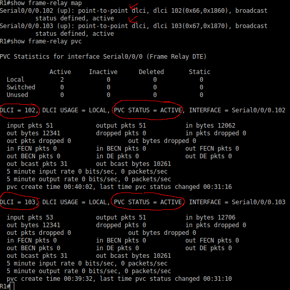
R1#ping 10.1.1.2
R1#ping 10.1.2.3
R2#show frame-relay map
R2#show frame-relay pvc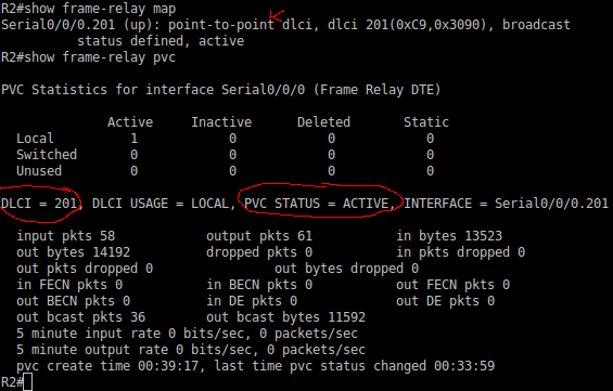
R2#ping 10.1.1.1
R2#ping 10.1.2.3
R3#show frame-relay map
R3#show frame-relay pvc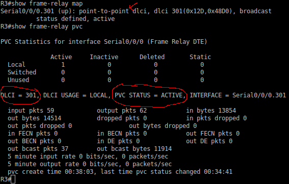
R3#ping 10.1.1.1
R3#ping 10.1.1.2


 Our Central Office subnets = 172.16.0.0 – 172.16.88.0


