View Modes and Router Basics

Objective: This lab will provide the understanding of how to login via the console port of a router view sub commands of user mode, privilege mode, global configuration mode, and the various sub modes. You will also configure the basic information needed to get a router ready for installation in a network.

Purpose: To observe the various sub commands available in each mode of Cisco router and have the ability to configure the basic info all Jr. network engineer need to have.

Topology:

console

Task 1: Use the proper cable to connect the ports as shown in the topology.
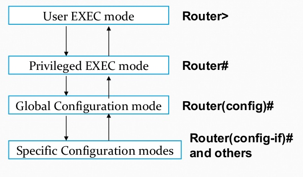
Login to the router in user mode.
Enter privileged  mode and view the list of available sub commands.
Enter global configuration mode and view the list of available sub commands.
Enter interface configuration mode and view sub commands.
Enter line console mode and view sub commands.

Task 2:  Configure host name as shown in the topology.
Take note of how your prompt has changed.

Task 3: Set the interface serial 0/1 ip address to 192.168.10.1 /24
Use the correct subnet mask as given from the CIDR notation.

Task 4: Set the password for console to cisco
test console password by logging out and back into console.

Task 5: View running and startup configurations.
Note the differences. Remember RAM stores the running configuration and is volatile memory that is erased at reload or power off and NVRAM stores startup configuration and is only affected by being overwritten or erased.
Copy running configuration to startup configuration
View startup configuration again and note how it has changed to reflect the running configuration.

Notes: You can also copy from startup configuration to running configuration but it generally only adds to the running configuration it does not delete running configuration when copied.
Other useful commands to know are how to copy stratup configuration to TFTP server and copy tftp server to running configuration

modes

ANSWER:

Task 1:
We need to use a rollover cable to connect the two devices also known as a Cisco console cable. Once logged in you will be at the user mode
Router>
Router>en
Router#?
Router#configure  terminal
Router(config)#?
Router(config)#exit
Router#configure interface
Router(config-if)#?
Router(config-if)#exit
Router#configure terminal
Router(config)#line con 0
Router(config-line)#?
Router(config-line)#end

Task 2:
Router#configure terminal
Router(config)#hostname R1
R1(config)#

Task 3:
R1(config)#interface s0/1
R1(config-if)#ip address 192.168.10.1 255.255.255.0
R1(config-if)#no shut
R1(config-if)#exit

Task 4:
R1(config)#line console 0
R1(config-line)#login
R1(config-line)#password cisco
R1(config-line)#end
R1#exit
password:

Task 5:
R1>en
R1#show running-config
R1#show startup-config
R1#copy running-config startup-config
R1#show startup-config

Home Lab Build Guide

There is no longer a reason to own physical hardware to create Cisco labs for your CCNA. The modern recommendation is to purchase Cisco VIRL and download the virtaul images for GNS3. I also recommend purchasing VMWare Workstation Pro for running virtual labs.

If you are just looking to get the CCNA cert and do not plan a making a career as a network engineer then virtualizing labs with GNS3 or Packet Tracer for CCNA will work fine for you. If you do plan on building a career in networking than I strongly recommend building a physical lab. There are many things that happen in a physical lab that you do not get to experience with a virtual lab. In a physical lab you have to make and choose correct cables, you can watch what the router or switch is doing by looking at the lights, interfaces sometimes fail, learning how to upgrade IOS versions, doing password recovery etc… Below I have two lists for what equipment to get for a CCNA lab and equipment to get if you plan on going to CCNP after.

Basic CCNA Lab (IOS version 12.4 will work for CCNA level)
2x 2950 switches
2x 2811 routers

Cables:
3x Straight Ethernet
4x Crossover Ethernet
2x Serial Crossover
1x Rollover (console)
4x Power

As of November 2015 you can get 2950’s on ebay for under $20 and the 2811’s can be found for $50 – $100 each.

Advanced CCNA to CCNP lab (look for equipment that supports IOS version 15)
3x 2960 switches
3x 2811 routers

Cables:
5x Straight Ethernet
5x Crossover Ethernet
3x Serial Crossover
1x Rollover (console)
6x Power

As of November 2015 you can get 2960’s on ebay for right around $40 and the 2811’s can be found for $50 – $100 each.

STP port states

Objective: Verify and view the different Spanning Tree Protocol port states, i.e Listening, Learning, Forwarding.

Purpose: To be able to understand STP port operation from Blocked -> Listening -> Learning -> Forwarding. A switched network is fully converged when all ports are either in forwarding or blocking state.

Topology:

vlan

Task 1: Use the proper cable to connect the ports as shown in the topology.

Task 2:  Configure host names  on the switch and the router as shown in the topology.

Task 3: Configure SW1 as VTP server and set VTP domain to CISCO with a password of CISCO.

Task 4: Configure SW1 with the VLAN as shown in the topology and configure the correct interface for the VLAN. Configure the IP address on SW1 as shown in topology.

Task 5: Configure the IP address on R1 as shown in topology. (do not use a subnet calculator). Ping the interface on SW1 to verify connection.

Task 6: On SW1, view spanning-tree status. Then issue a shut command on interface f0/2 and then issue a no shut and quickly view spanning-tree status again. Refresh the spanning-tree view every couple of seconds to watch the states change from LIS, LRN, FWD. Take note of how the port goes through each state.


ANSWER:

Task 1:
We need to use a regular straight through cable to connect the two devices.

Task 2:
Switch>en
Switch#conf t
Switch(config)#hostname SW1
SW1(config-t)#

Router>en
Router#conf t
Router(config)#hostname R1
R1(config)#

Task 3:
SW1(config)#vtp server
SW1(config)#vtp domain CISCO
SW1(config)#vtp password CISCO

Task 4:
SW1(config)#vlan 10
SW1(config-vlan)#name SALES
SW1(config-vlan)#int f0/2
SW1(config-if)#switchport mode access
SW1(config-if)#switchport  access vlan 10
SW1(config-if)#int vlan 10
SW1(config-if)#ip address 172.16.0.2 255.255.255.252
SW1(config-if)#no shut
SW1(config-if)#exit
SW1(config)#exit
SW1#

Task 5:
R1(config)#int f0/0
R1(config-if)#ip address 172.16.0.1 255.255.255.252
R1(config-if)#no shut
R1(config-if)#ping 172.16.0.1

Task 6:
SW1#show spanning-tree

fwd1

SW1#conf t
SW1(config)#int f0/2
SW1(config-if)#shut
SW1(config-if)#no shut
SW1(config-if)#Ctrl z
SW1# show spanning-tree

lis

SW1# show spanning-tree

lrn

SW1# show spanning-tree

fwd


Blocking State

The Switch Ports will go into a blocking state at the time of election process, when a switch receives a BPDU on a port that indicates a better path to the Root Switch (Root Bridge), and if a port is not a Root Port or a Designated Port.

A port in the blocking state does not participate in frame forwarding and also discards frames received from the attached network segment. During blocking state, the port is only listening to and processing BPDUs on its interfaces. After 20 seconds, the switch port changes from the blocking state to the listening state.

Listening State

After blocking state, a Root Port or a Designated Port will move to a listening state. All other ports will remain in a blocked state. During the listening state the port discards frames received from the attached network segment and it also discards frames switched from another port for forwarding. At this state, the port receives BPDUs from the network segment and directs them to the switch system module for processing. After 15 seconds, the switch port moves from the listening state to the learning state.

Learning State

A port changes to learning state after listening state. During the learning state, the port is listening for and processing BPDUs . In the listening state, the port begins to process user frames and start updating the MAC address table. But the user frames are not forwarded to the destination. After 15 seconds, the switch port moves from the learning state to the forwarding state.

Forwarding State

A port in the forwarding state forwards frames across the attached network segment. In a forwarding state, the port will process BPDUs , update its MAC Address table with frames that it receives, and forward user traffic through the port. Forwarding State is the normal state. Data and configuration messages are passed through the port, when it is in forwarding state.

Disabled State

A port in the disabled state does not participate in frame forwarding or the operation of STP because a port in the disabled state is considered non-operational.

VTP Transparent Mode

Objective: Configure VTP Transparent mode on Catalyst switches. Default mode for Cisco switches is Server mode.

Purpose: Learn how VTP configuration is not propagated across a trunk when switches are set to VTP transparent on the same VTP domain.

Topology:

topo

Task 1: Use the proper cables to connect the ports as shown in the topology.

Task 2:  Configure host names  on both switches as shown in the topology.

Task 3: Set SW1 as VTP Transparent and SW2 as VTP Transparent. Create VLANs as shown in topology on SW1 and SW2. Put both switches in VTP domain named CISCO. Verify VTP mode and domain.

Task 4: Make the link between the switches a 802.1q trunk link. Verify the link is now a trunk link.

Task 5: Assign the correct interfaces to the correct VLANs. Verify VLAN and interfaces. Notice that each switch has it’s own VLAN configuration (not propagated over trunk).

Task 6: Configure R1 and R2 with correct host names and assign proper IP addresses with correct subnet mask of /28 without using a subnet calculator. Ping from R1 to R2 and R2 to R1.


ANSWER:

Task 1:
We need to use a crossover cable to connect the two switches because they are two like devices. Then use a straight through cable for the connections from the routers to the switches.

Task 2:
Switch>en
Switch#conf t
Switch(config)#hostname SW1
SW1(config)#

Switch>en
Switch#conf t
Switch(config)#hostname SW2
SW2(config)#

Task 3:
SW1(config-t)#vtp mode transparent
SW1(config)#vlan 2010
SW1(config-vlan)#name SALES
SW1(config-vlan)#vlan 2030
SW1(config-vlan)#name MANAGERS
SW1(config-vlan)#vtp domain CISCO
SW1(config-vlan)#exit
SW1(config)#exit
SW1#show vtp status

SW2(config)#vtp mode transparent
SW2(config)#vlan 2010
SW2(config-vlan)#name SALES
SW2(config-vlan)#vlan 2040
SW2(config-vlan)#name DIRECTORS
SW2(config-vlan)#vtp domain CISCO
SW2(config-vlan)#exit
SW2(config)#exit
SW2#show vtp status

Task 4:
SW1(config)#int f0/1
SW1(config-if)#switchport trunk encapsulation dot1q
SW1(config-if)#switchport mode trunk
SW1(config-if)#exit
SW1(config)#exit
SW1#show int trunk

SW2(config)#int f0/1
SW2(config-if)#switchport trunk encapsulation dot1q
SW2(config-if)#switchport mode trunk
SW2(config-if)#exit
SW2(config)#exit
SW2#show int trunk

Task 5:
SW1#conf t
SW1(config)#int f0/2
SW1(config-if)#switchport mode access
SW1(config-if)#switchport access vlan 2010
SW1(config-if)#exit
SW1(config)#exit
SW1#show vlan brsw1trans

SW2#conf t
SW2(config)#int f0/2
SW2(config-if)#switchport mode access
SW2(config-if)#switchport access vlan 2010
SW2(config-if)#exit
SW2(config)#exit
SW2#show vlan br

if you get the below for output then you need to remove the unwanted ports by doing a no switchport access on the interfaces that where auto assigned to the VLANs.

sw2port

Task 6:
Router>en
Router#conf t
Router(config)#hostname R1
R1(config)#int f0/0
R1(config-if)#ip address 172.16.0.1 255.255.255.240
R1(config-if)#no shut
R1(config-if)#exit
R1(config)#exit
R1#ping 172.16.0.2

R1 ping

Router>en
Router#conf t
Router(config)#hostname R2
R2(config)#int f0/0
R2(config-if)#ip address 172.16.0.2 255.255.255.240
R2(config-if)#no shut
R1(config-if)#exit
R1(config)#exit
R1#ping 172.16.0.2

VTP Server and Client

Objective: Configure VTP Server and Clients mode on Catalyst switches. Default mode for Cisco switches is Server mode.

Purpose: Learn how VTP configuration is propagated from VTP servers to VTP clients on the same VTP domain.

Topology:

lab

Task 1: Use the proper cables to connect the ports as shown in the topology.

Task 2:  Configure host names  on both switches as shown in the topology.

Task 3: Create VLANs as shown in topology on SW1. Set SW1 as VTP Server and SW2 as VTP Client. Put both switches in VTP domain named CISCO. Verify VTP mode and domain.

Task 4: Make the link between the switches a 802.1q trunk link. Verify the link is now a trunk link.

Task 5: Make fa0/2 on both switches an access port and assign it to VLAN 10. Verify VLAN config and ports assigned.

Task 6: Configure R1 and R2 with correct host names and assign proper IP addresses with correct subnet mask of /28 without using a subnet calculator.

Task 7: Ping from R1 to R2 and R2 to R1.


ANSWER:

Task 1:
We need to use a crossover cable to connect the two switches because they are two like devices. Then use a straight through cable for the connections from the routers to the switches.

Task 2:
Switch>en
Switch#conf t
Switch(config)#hostname SW1
SW1(config)#

Switch>en
Switch#conf t
Switch(config)#hostname SW2
SW2(config)#

Task 3:
SW1(config)#vtp mode server
SW1(config)#vlan 10
SW1(config-vlan)#name SALES
SW1(config-vlan)#vlan 20
SW1(config-vlan)#name MANAGERS
SW1(config-vlan)#vtp domain CISCO
SW1(config-vlan)#exit
SW1(config)#exit
SW1#show vtp status

sw1vtp

SW2(config)#vtp mode client
SW2(config-vlan)#vtp domain CISCO
SW2(config-vlan)#exit
SW2(config)#exit
SW2#show vtp status

sw2vtp

Task 4:
SW1(config)#int f0/1
SW1(config-if)#switchport trunk encapsulation dot1q
SW1(config-if)#switchport mode trunk
SW1(config-if)#exit
SW1(config)#exit
SW1#show int trunk

sw1trunk

SW2(config)#int f0/1
SW2(config-if)#switchport trunk encapsulation dot1q
SW2(config-if)#switchport mode trunk
SW2(config-if)#exit
SW2(config)#exit
SW2#show int trunk

sw2trunk

Task 5:
SW1#conf t
SW1(config)#int f0/2
SW1(config-if)#switchport mode access
SW1(config-if)#switchport access vlan 10
SW1(config-if)#exit
SW1(config)#exit
SW1#show vlan br

sw1vlanpng

SW2#conf t
SW2(config)#int f0/2
SW2(config-if)#switchport mode access
SW2(config-if)#switchport access vlan 10
SW2(config-if)#exit
SW2(config)#exit
SW2#show vlan br

Task 6:
Router>en
Router#conf t
Router(config)#hostname R1
R1(config)#int f0/0
R1(config-if)#ip address 172.16.0.1 255.255.255.240
R1(config-if)#no shut
R1(config-if)#exit
R1(config)#exit
R1#ping 172.16.0.2

R1 ping

Router>en
Router#conf t
Router(config)#hostname R2
R2(config)#int f0/0
R2(config-if)#ip address 172.16.0.2 255.255.255.240
R2(config-if)#no shut
R1(config-if)#exit
R1(config)#exit
R1#ping 172.16.0.2

Extended VLAN Lab

Objective: This lab will provide the understanding of how to configure extended VLANs 10006 – 4096  on Catalyst switches. Creating VLANs is a fundamental skill that network engineers need to be able to perform.

Purpose: VLANs allow you to segment your network into smaller broadcast domains.

Topology:

ex

Task 1: Use the proper cable to connect the ports as shown in the topology.

Task 2:  Configure host names  on both switches as shown in the topology.

Task 3: Create VLANs as shown in topology on both switches. Remember the default VTP mode is Server and you can only create extended VLANs in Transparent or Client mode.

Task 4: Configure ports as shown in topology as access ports and assign them to correct VLANs.

Task 5: Verify VLAN configuration using correct IOS commands.

Your config should resemble below when done with the lab.

extvlan

ANSWER:

Task 1:
We need to use a crossover cable to connect two like devices.

Task 2:
Switch>en
Switch#conf t
Switch(config-t)#hostname SW1
SW1(config)#

Switch>en
Switch#conf t
Switch(config)#hostname SW2
SW2(config)#

Task 3:
SW1(config)#vtp mode transparent
SW1(config)#vlan 2010
SW1(config-vlan)#name SALES
SW1(config-vlan)#vlan 2020
SW1(config-vlan)#name MANAGERS
SW1(config-vlan)#vlan 2030
SW1(config-vlan)#name ENGINEERS
SW1(config-vlan)#vlan 2040
SW1(config-vlan)#name SUPPORT

SW2(config)#vtp mode transparent
SW2(config)#vlan 2010
SW2(config-vlan)#name SALES
SW2(config-vlan)#vlan 2020
SW2(config-vlan)#name MANAGERS
SW2(config-vlan)#vlan 2030
SW2(config-vlan)#name ENGINEERS
SW2(config-vlan)#vlan 2040
SW2(config-vlan)#name SUPPORT

Task 4:
SW1(config)#int f0/5
SW1(config-if)#switchport mode access
SW1(config-if)#switchport access vlan 2010
SW1(config-if)#int f0/6
SW1(config-if)#switchport mode access
SW1(config-if)#switchport access vlan 2020
SW1(config-if)#int f0/7
SW1(config-if)#switchport mode access
SW1(config-if)#switchport access vlan 2020
SW1(config-if)#int f0/8
SW1(config-if)#switchport mode access
SW1(config-if)#switchport access vlan 2030

SW2(config)#int f0/5
SW2(config-if)#switchport mode access
SW2(config-if)#switchport access vlan 2010
SW2(config-if)#int f0/6
SW2(config-if)#switchport mode access
SW2(config-if)#switchport access vlan 2020
SW2(config-if)#int f0/7
SW2(config-if)#switchport mode access
SW2(config-if)#switchport access vlan 2020
SW2(config-if)#int f0/8
SW2(config-if)#switchport mode access
SW2(config-if)#switchport access vlan 2030

Task 5:
SW1#show vlan br

SW2#show vlan br

Configuring Standard VLAN

Objective: This lab will provide the understanding of how to configure standard VLANs 1 – 10001 on Catalyst switches. Creating VLANs is a fundamental skill that network engineers need to be able to perform.

Purpose: VLANs allow you to segment your network into smaller broadcast domains.

Topology:

VLNA standard

Task 1: Use the proper cable to connect the ports as shown in the topology.

Task 2:  Configure host names  on both switches as shown in the topology.

Task 3: Create VLANs as shown in topology on both switches. (repetition is key to learning IOS commands)

Task 4: Configure ports as shown in topology as access ports and assign them to correct VLANs.

Task 5: Verify VLAN configuration using correct IOS commands.

Your config should resemble below when done with the lab.

vlan stan final

ANSWER:

Task 1:
We need to use a crossover cable to connect two like devices.

Task 2:
Switch>en
Switch#conf t
Switch(config)#hostname SW1
SW1(config)#

Switch>en
Switch#conf t
Switch(config)#hostname SW2
SW2(config)#

Task 3:
SW1(config)#vlan 10
SW1(config)#name SALES
SW1(config)#vlan 20
SW1(config-vlan)#name MANAGERS
SW1(config-vlan)#vlan 30
SW1(config-vlan)#name ENGINEERS
SW1(config-vlan)#vlan 40
SW1(config-vlan)#name SUPPORT
SW1(config-vlan)#exit

SW2(config)#vlan 10
SW2(config)#name SALES
SW2(config)#vlan 20
SW2(config-vlan)#name MANAGERS
SW2(config-vlan)#vlan 30
SW2(config-vlan)#name ENGINEERS
SW2(config-vlan)#vlan 40
SW2(config-vlan)#name SUPPORT
SW2(config-vlan)#exit

Task 4:
SW1>en
SW1#conf t
SW1(config)#int f0/5
SW1(config-if)#switchport mode access
SW1(config-if)#switchport access vlan 10
SW1(config-if)#int f0/6
SW1(config-if)#switchport mode access
SW1(config-if)#switchport access vlan 20
SW1(config-if)#int f0/7
SW1(config-if)#switchport mode access
SW1(config-if)#switchport access vlan 30
SW1(config-if)#int f0/8
SW1(config-if)#switchport mode access
SW1(config-if)#switchport access vlan 40

SW2>en
SW2#conf t
SW2(config)#int f0/5
SW2(config-if)#switchport mode access
SW2(config-if)#switchport access vlan 10
SW2(config-if)#int f0/6
SW2(config-if)#switchport mode access
SW2(config-if)#switchport access vlan 20
SW2(config-if)#int f0/7
SW2(config-if)#switchport mode access
SW2(config-if)#switchport access vlan 30
SW2(config-if)#int f0/8
SW2(config-if)#switchport mode access
SW2(config-if)#switchport access vlan 40

Task 5:
SW1#show vlan br

SW2#show vlan br


Stop Watch Game

Our mini-project for this week will focus on combining text drawing in the canvas with timers to build a simple digital stopwatch that keeps track of the time in tenths of a second. The stopwatch should contain “Start”, “Stop” and “Reset” buttons. To help guide you through this project, we suggest that you download the provided program template for this mini-project and build your stopwatch program.

http://www.codeskulptor.org/#user40_2Il0zENJy6_12.py

stop

# template for “Stopwatch: The Game”
import simplegui

# define global variables
mins = 0
sec = 0
count = 0
x = 0
y = 0
s = 0
z = 0

# define helper function format that converts time
# in tenths of seconds into formatted string A:BC.D
def format(t):
global count, sec, mins
t = count
if (t == 10):
sec += 1
count = 0
if (sec == 60):
mins += 1
sec = 0

# define event handlers for buttons; “Start”, “Stop”, “Reset”
def start_timer():
global s, z
if s-z == 0:
s += 1
timer.start()

def stop_timer():
global x, y, s, z
if s-z == 1:
z += 1
timer.stop()
y += 1
if count == 0 :
x += 1

def reset_timer():
global count, sec, mins, x, y, s, z
timer.stop()
mins = 0
sec = 0
count = 0
x = 0
y = 0
s = 0
z = 0

def exit_timer():
frame.stop()

# define event handler for timer with 0.1 sec interval
def timer_handler():
global count
count += 1

def draw_handler(canvas):
global count, sec, min, x, y
format(count)
canvas.draw_text(str(x) + “/” + str(y), (135,30), 30, “Green”)
if (sec < 10):
canvas.draw_text(str(mins) + “:” + “0” + str(sec) + “.” + str(count),(60,100), 30, “White”)
else:
canvas.draw_text(str(mins) + “:” + str(sec) + “.” + str(count),(60,100), 30, “White”)

# create frame
frame = simplegui.create_frame(“Stopwatch: The Game “, 200, 200)

# register event handlers
timer = simplegui.create_timer(100, timer_handler)
frame.add_button(“Start”, start_timer, 100)
frame.add_button(“Stop “, stop_timer, 100)
frame.add_button(“Reset”, reset_timer, 100)
frame.add_button(“Exit “, exit_timer, 100)
frame.set_draw_handler(draw_handler)

# start frame
frame.start()

Rock Paper Scissors Lizard Spock

Rock-paper-scissors is a hand game that is played by two people. The players count to three in unison and simultaneously “throw” one of three hand signals that correspond to rock, paper or scissors. The winner is determined by the rules:

  • Rock smashes scissors
  • Scissors cuts paper
  • Paper covers rock

Rock-paper-scissors is a surprisingly popular game that many people play seriously (see the Wikipedia article for details). Due to the fact that a tie happens around 1/3 of the time, several variants of Rock-Paper-Scissors exist that include more choices to make ties less likely.

Rock-paper-scissors-lizard-Spock (RPSLS) is a variant of Rock-paper-scissors that allows five choices. Each choice wins against two other choices, loses against two other choices and ties against itself. Much of RPSLS’s popularity is that it has been featured in 3 episodes of the TV series “The Big Bang Theory”. The Wikipedia entry for RPSLS gives the complete description of the details of the game.

http://www.codeskulptor.org/#user40_f9k1bpSwYP_6.py

spock

# Rock-paper-scissors-lizard-Spock template

# The key idea of this program is to equate the strings
# “rock”, “paper”, “scissors”, “lizard”, “Spock” to numbers
# as follows:
#
# 0 – rock
# 1 – Spock
# 2 – paper
# 3 – lizard
# 4 – scissors

# helper functions

import random

def name_to_number(name):
# delete the following pass statement and fill in your code below
if name == “rock”:
return 0
elif name == “Spock”:
return 1
elif name == “paper”:
return 2
elif name == “lizard”:
return 3
else:
return 4

# convert name to number using if/elif/else
# don’t forget to return the result!

def number_to_name(number):
# delete the following pass statement and fill in your code below
if number == 0:
return “rock”
elif number == 1:
return “Spock”
elif number == 2:
return “paper”
elif number == 3:
return “lizard”
else:
return “scissor”

# convert number to a name using if/elif/else
# don’t forget to return the result!

def rpsls(player_choice):
# delete the following pass statement and fill in your code below

# print a blank line to separate consecutive games
print””

# print out the message for the player’s choice
print “Player chooses”, player_choice

# convert the player’s choice to player_number using the function name_to_number()
player_number = name_to_number(player_choice)

# compute random guess for comp_number using random.randrange()
comp_number = random.randrange(0,(4+1))

# convert comp_number to comp_choice using the function number_to_name()
comp_choice = number_to_name(comp_number)

# print out the message for computer’s choice
print “Computer chooses”, comp_choice

# compute difference of comp_number and player_number modulo five
difference = (comp_number – player_number) % 5

# use if/elif/else to determine winner, print winner message
if difference == 0:
output = “Player and Computer Tie”
elif difference == 1 or difference == 2:
output = “Computer wins!”
else:
output = “Player wins!”

print output

# test your code – THESE CALLS MUST BE PRESENT IN YOUR SUBMITTED CODE
rpsls(“rock”)
rpsls(“Spock”)
rpsls(“paper”)
rpsls(“lizard”)
rpsls(“scissors”)

# always remember to check your completed program against the grading rubric

Guess the Number Game

One of the simplest two-player games is “Guess the number”. The first player thinks of a secret number in some known range while the second player attempts to guess the number. After each guess, the first player answers either “Higher”, “Lower” or “Correct!” depending on whether the secret number is higher, lower or equal to the guess. In this project, you will build a simple interactive program in Python where the computer will take the role of the first player while you play as the second player.

When discussing ranges in this mini-project, we will follow the standard Python convention of including the low end of the range and excluding the high end of the range. Mathematically, we will express ranges via the notation [low, high). The square bracket of the left of the range indicates that the corresponding bound should be included. The left parenthesis on the right of the range indicates that corresponding bound should be excluded. For example, the range [0, 3) consists of numbers starting at 0 up to, but not including 3. In other words 0, 1, and 2.

You will interact with your program using an input field and several buttons. For this project, we will ignore the canvas and print the computer’s responses in the console. Building an initial version of your project that prints information in the console is a development strategy that you should use in later projects as well. Focusing on getting the logic of the program correct before trying to make it display the information in some “nice” way on the canvas usually saves lots of time since debugging logic errors in graphical output can be tricky.

http://www.codeskulptor.org/#user40_cUnGywGYKp_6.py

guess

# template for “Guess the number” mini-project
# input will come from buttons and an input field
# all output for the game will be printed in the console

import simplegui
import random
import math

# initialize global variables used in your code here
num_range = 100
secret_number = 0
guesses = 0

# helper function to start and restart the game
def new_game():
global num_range
global secret_number
global guesses

if num_range == 100 :
guesses = 7
elif num_range == 1000 :
guesses = 10

secret_number = random.randrange(0, num_range)

print “”
print “New game. Range is from 0 to “, num_range
print “Number of reamining guesses is”, guesses
pass

# define event handlers for control panel
def range100():
global num_range
# button that changes the range to [0,100) and starts a new game
num_range = 100
new_game()
pass

def range1000():
global num_range
# button that changes the range to [0,1000) and starts a new game
num_range = 1000
new_game()
pass

def get_input(guess):
global guesses
global secret_number

# main game logic goes here
winner = False

print “Guess was “, guess
guesses = guesses – 1
print “Number of remaining guesses is “, guesses

if int(guess) == secret_number:
winner = True
elif int(guess) > secret_number:
output = “Lower!”
else:
output = “Higher!”

if winner:
print “Correct! \n”
new_game()
return

elif guesses == 0:
print “You ran out of guesses. The number was”, secret_number
new_game()
return
else:
print output
pass

# create frame
frame = simplegui.create_frame(“Guess the number:”, 200 ,200)

# register event handlers for control elements and start frame
frame.add_button(“Range is [0, 100)”, range100, 200)
frame.add_button(“Range is [0, 1000)”, range1000, 200)
frame.add_input(“Enter a guess”, get_input, 200)

# call new_game
new_game()

frame.start